
There are several different schools of thought on exhaust design, but, because we employ high-revving road bike engines, we require an increase in mid range, and overall torque output, so we can discard some of the formulae that are used to produce maximum horsepower.
As bikes are relatively light, the engines don’t need to put out very high torque figures, they aim for high horsepower. Increasing the length of the primaries will improve torque and flexibility, and a bike-engined buggy needs more low – mid range than in the bike because of the extra weight and driving style.
With bike engines, some of the peaky torque can be moved down the range by using smaller diameter primary pipes. One increment down can alter the peak torque by around 500 RPM.
To establish the best length of primaries for your specific engine, you will need to know the exhaust valve timing, and the revs at peak torque. The bike’s manual or owner’s handbook should provide these two figures.
This formula will then approximate your requirements:
Note: The primaries are measured from the head of the exhaust valve and not the flange seat on the outside of the exhaust port. This is because different head designs have different lengths of ports.
L = (850 X ED) / RPM
L = length of primary pipes in inches
ED = 180 degrees + number of degrees exhaust valve opens BBDC
RPM = engine RPM at peak torque
The length of the secondaries should be approximately two thirds of the length of the primaries.
Tools required
- Abrasive cut-off saw.
- Belt sander (80 grit).
- Deburring tool.
- Duct tape to hold pipes in place.
- Exhaust tube expander (not absolutely necessary, but really handy).
- Hack saw, for breaking tack-welds (if necessary).
- Half round file.
- Hammer.
- Hose clamps to hold pipes in place.
- Permanent felt tip marker pen.
- Scissors.
- Narrow tape measure, dressmaker’s (soft plastic), 6mm (¼”) wide.
- T-square.
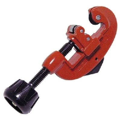
- Tube cutter (wheel type).
Materials required
- Original exhaust system, and/or straight lengths and bends of mild steel or stainless steel tube, in various diameters.
- Some off-cuts of 32mm X 3mm flat bar.
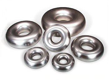
- Some donuts of suitable OD (if you find you need really tight bend radii).
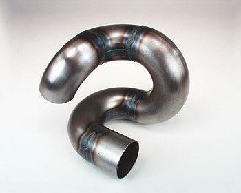
The terminology used to describe exhaust systems can be confusing, as the individual elements are normally referred to as “pipes”, whereas they are actually thin-wall tubes.
The techniques described here apply equally to single or twin cylinder engines as they do to four cylinder engines, though as most will be utilizing the latter, it is the four cylinder headers that will be focused on. Mild steel exhaust tube conducts roughly 220% more heat per foot than stainless steel exhaust tube, and as exhaust gases travel through a mild steel system they cool down, thereby losing velocity. By keeping the exhaust hot, the velocity will be higher, resulting in a better scavenging effect. Reverse flow will be reduced at lower rpm too. A good way of keeping the heat in a mild steel exhaust system, is to coat the system inside and out, with a thermal coating such as Jet Hot.
More heat stays inside stainless header tubes which can be beneficial; by not allowing the contraction of the cooling gases as they flow down the tubes, more exhaust velocity is retained which promotes better scavenging. This retention of velocity increases the overall header efficiency.
304 is the most common, and cheapest grade of stainless steel suitable for headers of normally aspirated engines, but if running a forced induction engine, a better option would be 321 stainless, as it withstands much higher temperatures, and has greater fatigue resistance.
There’s no doubt, a stainless system will both look and perform better, but cost and the ability to weld stainless could be a factor. TIG welding would be the first choice, but MIG welding would be fine. MIG welding stainless steel requires using pure argon gas, and the appropriate stainless wire. Gas welding is of course another option.
The deciding factor will probably be the material used for the bike engine’s original system (you can test it with a magnet), as it’s often easiest to just cut the tops off the bike’s primary pipes, and use them to start the new headers. If the bike’s headers are stainless, and you don’t want to use stainless for the system, then making the entire system, from the primaries onwards, is your only option.
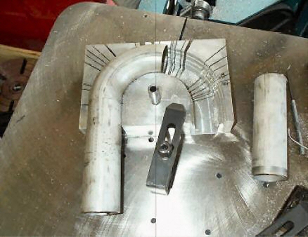
Whichever method you choose, start off with the same primary diameters as on the bike (unless the engine’s below 1000cc…see above), measuring the bends about their centre lines. Cut new bend segments slightly oversize, and then grind or sand them square and true. Where room permits, a wheel type pipe cutter can be used to score a feint line around the tube as a cutting guide.
Try to maintain the bend radius across joints, and don’t “cheat” the radius. Make a cardboard template of the inside radius of the bends being used. This template can be held up to the inside of joints in bends as a guide for flowing the overall transition. A machined aluminium jig to support the tube and a bandsaw is an accurate way to cut bend segments.
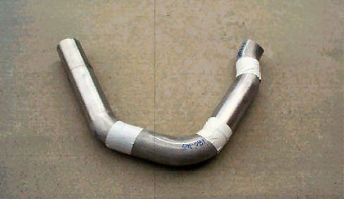
When trial fitting bend segments together, make several “witness” lines across the joins with the felt tip pen to “clock” the joints. Despite the temptation to weld the pipes as you go, just use some hose clamps with “windows” drilled and filed in them, so you can tack weld through the windows.
Alternatively, use strips of masking tape across the sections to hold themtogether. Use a pair of scissors to cut narrow strips of tape (narrow strips holding the sections together will leave room for tack-welds). Only when you’re certain a series of sections are correctly positioned, should you tack-weld them together before moving on.
If you are going to make the entire system, then first measure the diameter and length of the original port rings, and cut them from suitable tube (or even pipe). The port rings/first bends must be securely fastened to the cylinder head, using the correct exhaust gasket to obtain the right spacing, before any further fabrication.
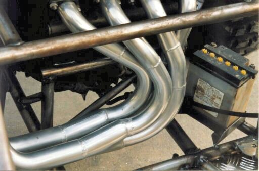
You will find there is more room on the right side of the R6 for the headers, also, the left side is a bit busy with the chain drive, gear change etc. It is imperative all four primary pipes are the same length as they enter the two “Y” pipes. The pipes from cylinders one and four are merged, and the pipes from two and three are merged. The “Y” pipes are made from tube one increment up from the primaries. The increments are usually around 3mm for metric tube, and ⅛” for imperial tube. So, if the primaries are Ø32mm then the “Y” pipes need to be made from Ø35mm tube. The secondaries are made from tube of the next increment up, and the tail pipe is again, made from the next increment up. The top ends of the connecting pipes can be expanded for a better fit, if required, with an exhaust tube expander.
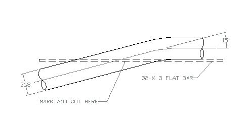
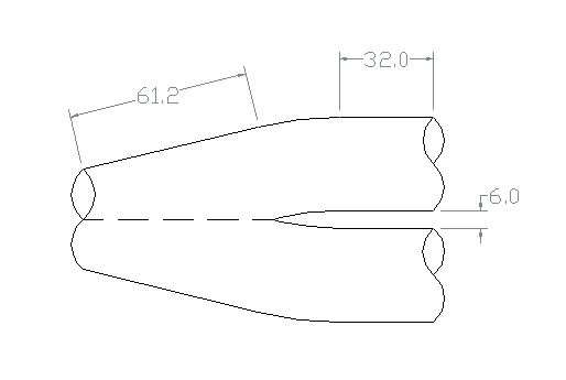
To make the primary “Y” pipes, take two lengths of tube, the same diameter as the primaries, in this example: Ø31.8mm X 1.6mm, and bend to 15 degrees. Lay one of the bends flat on the bench, and lay a strip of say 32mm X 3mm flat bar (or similar), on its edge, vertically along side the tube, on the inside of the bend, so as one end of the strip touches the bench, and the other end is raised up on top of the bend in the tube. Mark the bend in line with the flat bar, and cut along the edge of the flat bar, on the inside of the bend. Repeat with the second bend, and place the two cut bends, cut faces together, and carefully weld the two pieces together.
Group the primaries into pairs; cylinders #1 and #4 make up one pair, and cylinders #2 and #3 make up the second pair.
Cut and/or bend each pair of primaries so as their lower ends are parallel, and lined up with their respective “Y” pipes, and weld together. The welds should overlap by 0.5mm in the direction of flow to aid the gas’s escape.
Select two lengths of tube, suitable for the secondaries, and if necessary, bend them to shape.
Very slightly flatten the tops of the secondaries, to make their openings oval. Slip the secondaries over the ends of the primary “Y” pipes, and adjust their shape until they’re a snug fit. Mark where the ends of the secondaries meet the “Y” pipes then trim the “Y” pipes so they will just protrude into the secondaries by 0.5mm.
Make up a third “Y” pipe in the same manner as the others, but use tube of the next size up. This third “Y” pipe will slip over the ends of the secondaries by about 35mm, to aid dismantling of the system. Cut a length of tube for the tail pipe from the next incremental size, and attach it to the third “Y” pipe. The length of the tail pipe isn’t too critical, make it long enough to site the silencer in a convenient place.
Some means of holding the two parts of the system together will have to be made and attached to both parts. Bend four pieces of Ø2.5mm wire into long “U” shapes, and put a bend in them so the closed end of the “U” sits about 6mm up from the pipe, when the wires are laid on the exhaust. Weld the wires to the exhaust, using swivel-end exhaust springs to distance them correctly apart.
Either weld or slip a silencer on to the end of the tail pipe, and fit a silencer strap to its mid point, and hook on the springs to hold the exhaust together. Finally, make a suitable tab or bracket, weld it to the chassis, and bolt the silencer strap to it.
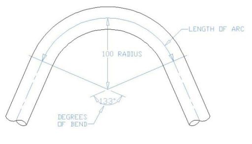
Length of curve:
L = (R x .01745) x Z
where:
L is the length,
R is radius of the tube bend,
Z is the angle of the bend.
or, to put it another way:
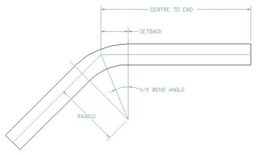
Length of tube in a Bend = CLR x DOB x 0.1745
Setback = Radius x Tangent ½ Angle of Bend
Circumference = 3.1416 x Diameter
Bend Allowance Calculator
Centre Line Radius
Degree of Bend
Bend allowance =
Exhaust part sources:
USA Stahl Headers
USA S&S Headers
USA Woolf
USA SPD
UK Custom Chrome
UK Zorstec
