
Before we get too entrenched in brake tech, just answer this: Which is the more powerful, the brakes or the engine? Well, in the case of a GSXR1000, it can do a standing quarter mile in 10.8 seconds with a terminal speed of 138mph, yet the brakes can do the same amount of work (but in reverse) in just 6.8 seconds!
The basics of the braking systems in the Rorty buggies have already been ironed out (pedal ratio, calliper size etc.), but there is scope for selecting custom master cylinder sizes and fitting brake bias valves and brake balance bars, if so desired.
Different conditions, driving styles and track layouts can all influence brake component choice, but before you start swapping things around lets clear up a few misunderstood braking fundamentals.
Unlike air, which can be compressed and will act like a spring giving a spongy feel to a brake pedal, fluid can not be compressed. Whatever amount of fluid is moved at one end of the brake system, will be transferred in total to the other end. The first principal of hydraulics is: pressure in equals pressure out. If 1.0 kg/cm² (14.2 psi) is applied at the master cylinder, then 1.0 kg/cm is what you get throughout the system. Pressure is a constant. The only variable (in a fault-free hydraulic system) is the force required to operate the brakes. For example, a master cylinder piston with a surface area of 1.0 cm² (0.155 psi), and with 10 kilos (22.05 lb) of force applied to it will produce 10 kilos of force per square centimetre – 10 kg/cm² (142.2 psi). If the calliper pistons have a surface area of 10 cm² (1.55sq inch) then the force there will be 10 x 10 kg, which will mean the callipers produce 100 kg of force. The pressure acting on the system is the same, in this case 10 kg/cm², but the force can be altered by changing the surface area of the callipers.
If the same 1.0 cm² master cylinder travels forward 1cm then the amount of fluid it displaces will be 1 cubic cm. If this fluid is then spread over the 10 square cm of calliper pistons, they will only be able to move 1/10th of a cm – 1mm. The force will be 100 kg (220.5 lb), but the calliper’s pistons may not move forward enough to grip the disc tightly and so give a weaker brake. This is often seen on some bikes that have a small master cylinder piston and two pot callipers which are then exchanged for six pot callipers. Again, the surface area increases and the force increases at the calliper but the small master cylinder only moves a small amount of fluid which in turn equates to a smaller movement of the calliper’s pistons.
The reverse can happen when running bike callipers with car type master cylinders.
Some bike callipers have double pots (two pistons in one side of the calliper and none on the other side of the disc), which operates as a single piston calliper, but with double the pressure (pressure x surface area of piston x number of pistons). When different sizes of piston are used in the same calliper, the larger diameter produces the higher brake pressure.
If there is only one piston on the inside and one on the outside of the disk (conventional twin pot calliper), they balance out and the force is pressure x surface of one piston. If the callipers all have identical sized pistons, the double piston calliper has a much higher advantage than a single piston calliper.
Master cylinders and callipers need to be carefully matched.
After some test driving, it may be apparent that braking efficiency needs to altered between front and rear axles to prevent one axle locking up before the other. This can be affected by the number of calliper pistons, their relative sizes and disc diameters. Variations in any of these can result in large changes felt during braking.
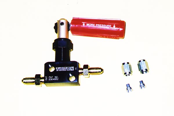
There are two methods of varying front to rear brake pressure. The simplest device is a brake bias valve, either fixed or adjustable. These are plumbed into the rear brake line to limit the pressure to the calliper, thus reducing braking effort on that line. The benefits are obvious. Bias valves are not affected by dirt jamming them, they are compact, and the seven-position lever type is very easily adjusted on the fly.
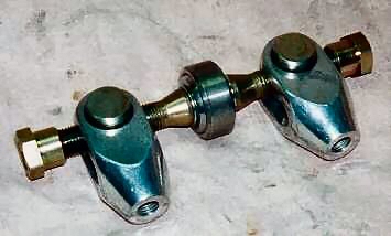
Check out this homemade bias valve too.
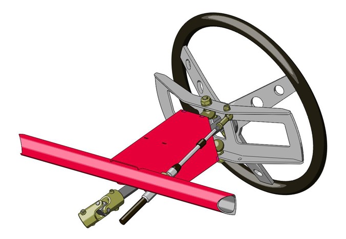
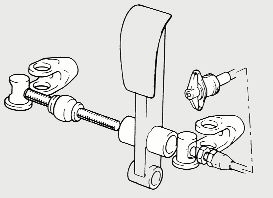
The second device, and most commonly found in bitumen cars, is the brake balance bar. The balance bar is simply a threaded rod inserted through a spherical bearing mounted in the brake pedal. The threaded rod operates two separate master cylinders via a clevis at each end which are attached to the master cylinders’ plunger rods. One cylinder operates the front brake circuit, and the other cylinder operates the rear circuit. The threaded rod can be rotated by means of a cable connected to a dash (or some handy point) mounted knob. When the knob/cable/rod is rotated, the pivot point is moved in favour of one of the pair of master cylinders.
When the balance bar is central, it spreads pedal pressure equally between both master cylinders creating equal pressure (given that the master cylinders are the same bore size). When fully adjusted toward one master cylinder it will afford approximately twice the pressure on that cylinder.
Adjustable balance bars offer plenty of adjustability for both front and rear circuits, but are not as reliable in off-road buggies, as the adjustment cable can seize and the bar itself can become jammed up with dirt.
Non adjustable bias pedals can be achieved with dual master cylinders by using unequal diameter master cylinders. If the master cylinders are unevenly matched, the smaller cylinder produces more line pressure for the same pedal pressure.
There is another approach to limiting brake line pressure that I came across years ago as Chief Scrutineer. One individual had taken a pair of Vice-Grips, and squeezed the metal brake line to reduce the flow. Expect severe retribution by the Scrutineer if caught doing this!
By the same token, routinely check all your lines to ensure there are no kinks or entrapments.
All brake pedals should incorporate a heavy return spring and a sturdy, adjustable return stop to prevent the piston hammering against the circlip. The pedal must be carefully adjusted also to ensure the internal piston seal actually advances far enough to prevent possible residual line pressure.
Pedal lengths and ratios are another area that can affect brake “feel” and the effort required to operate the brakes, though in the Rorty buggies, the ratios have been predetermined.
Brake Lines And Fittings.
Brake lines have basically two roles; to transfer brake fluid and to withstand pressures exceeding 12,000 PSI. To carry the fluid, all that’s required is a bore of 3/16″ (4.76mm) and to resist bursting, the tube needs to be made from some sort of tough, pliable material. The material also needs to be rigid enough not to straighten out any formed bends when pressure is applied to the brake pedal. Any bulging or straightening of the lines will result in loss of brake pedal “feel” and a reduction in brake efficiency.
Obviously some form of flexible tubing is required to transfer the fluid from the rigidly mounted lines in the car’s chassis across the suspension to the brake callipers or drums. Plain rubber hose would just expand and explode with the pressures involved, so production cars use hose assemblies that are reinforced with layers of rayon fabric. The automotive aftermarket has widely adopted the use of aeronautical grade flexible hose with an external stainless steel braid. This is accepted as the highest quality hose available and offers the best feel of any flexible hose.
Most production car brake systems are assembled from pre-bent sections of “Bundy” line (0.7mm wall brazed steel tube with a protective outer coating) and cadmium or zinc plated steel fittings. These components are sufficient for normal use and last quite well. Both Bundy line and the steel fittings are available in bulk from most auto shops, but there are a few aspects worth considering before making any purchase.
Steel brake lines, no matter what they’re coated with, are susceptible to corrosion because of the environment they are located in. The protective coating can easily be damaged by stray stones which can result in the steel line becoming rusted. Once rust sets in, the line’s ability to withstand high internal pressures is reduced and can further lead to complete failure.
Pure copper lines were used in early vehicles, and were much easier to bend and manipulate around the various corners and obstacles. However, copper on its own can easily crack due to vibration, but alloyed with another metal, and it makes probably the best brake line of all. Some high end and speciality cars use copper-nickel or copper-stainless brake lines, and again, this is readily available in coils from all the usual outlets.
The modern Kunifer alloy lines have a lower burst pressure than their steel counterpart, but are still tough enough and are virtually trouble free. Although these alloy lines are totally rust free, they are still quite stiff and require either a hand held or bench mounted device to make presentable bends.
I have spent many an hour trying to trace the source or cause of a spongy brake pedal. There’s nothing worse than a dead-feeling pedal in a highly tuned road car; not being able to sense the callipers doing their work against the discs. Off-road racing is a little different though. Some of the niceties of a well constructed braking system are lost to the extreme vibrations, banging and bouncing and general mayhem associated with racing a buggy. Even with the best rigid brake lines and flexible hoses, it’s not always possible to feel exactly what’s going on with the wheels on the track when the brake pedal is touched. That’s not to say care shouldn’t be taken to construct a sound braking system in a buggy, there is just a little room for alternative, more easily managed materials.
The central tube of the stainless braided hoses is nothing more than smooth bore P.T.F.E. tube. Smooth bore Nylon tube is available in 100 metre coils in the same sizes as Kunifer or Bundy line with minimum burst pressures of 1,000 and 2,500 PSI and it’s resistant to many solvents and chemicals including mineral and silicone brake fluids. Obviously we’ll require the higher rated version for the brake lines. It is a very easy task to thread one end of a coil of smooth bore through a chassis from the rear and attach it to a master cylinder. It can be bent to ridiculously small radii and simply held in position against the chassis with nothing more than 3mm (⅛”) cable ties. With irregular attachment, a long slow bend in smooth bore tube will try and straighten out when the pedal is applied. The secret is to make sure it is secured at regular intervals of about 100mm (4″). Tubing should avoid or be protected from exhaust systems or other areas of extreme heat.
Stainless braided hoses are not expensive if they are home assembled (as opposed to purchasing pre-assembled hoses). Even so, they still work out more expensive than just using all smooth bore tube. There’s no reason why the same smooth bore can’t be used to bridge the suspension to the callipers, as long as the tube is routed along the rear side of the wishbone tube and out of harms way.
Smooth bore Nylon tube is assembled in more or less the same way as other compression tube systems with one exception. In addition to the standard range of compression fittings, an special olive must be used that bites into the plastic tubing. Apart from the olives, it goes together like any other compression tubing and there are a vast array of fittings and adaptors available for just about every conceivable scenario.
